
 EN
EN
 ar
ar bg
bg hr
hr cs
cs da
da nl
nl fi
fi fr
fr de
de el
el hi
hi it
it ko
ko no
no pl
pl pt
pt ro
ro ru
ru es
es sv
sv tl
tl iw
iw id
id lv
lv lt
lt sr
sr sk
sk sl
sl uk
uk vi
vi et
et hu
hu th
th tr
tr fa
fa ms
ms hy
hy ka
ka ur
ur bn
bn mn
mn ta
ta kk
kk uz
uz ku
ku
diagram 4 wire load cell wire connection
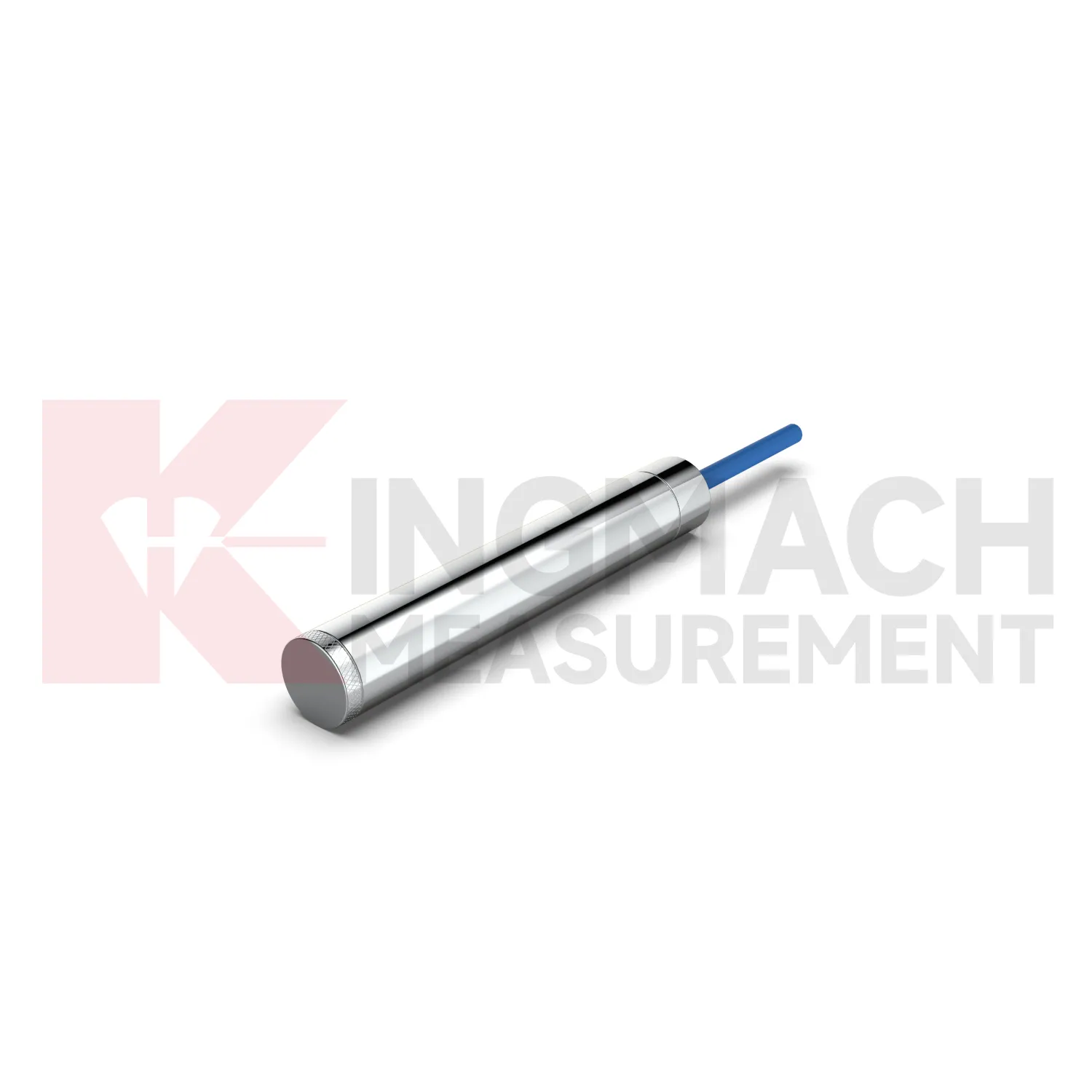
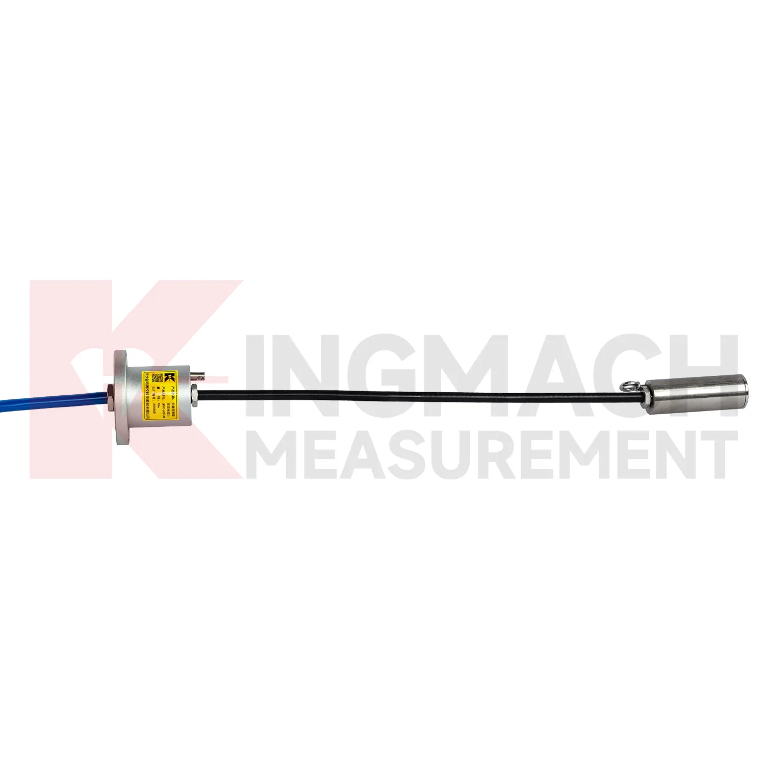
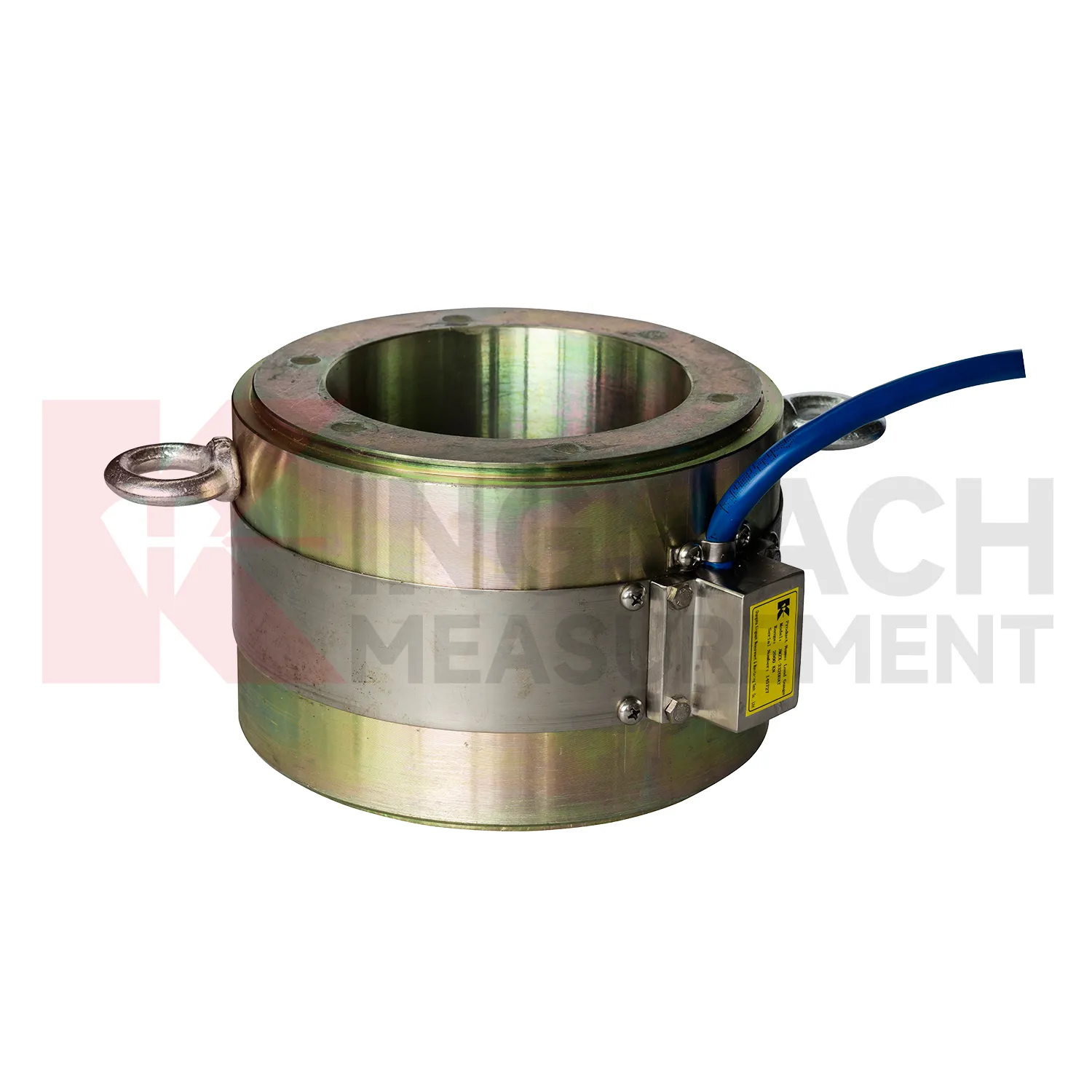
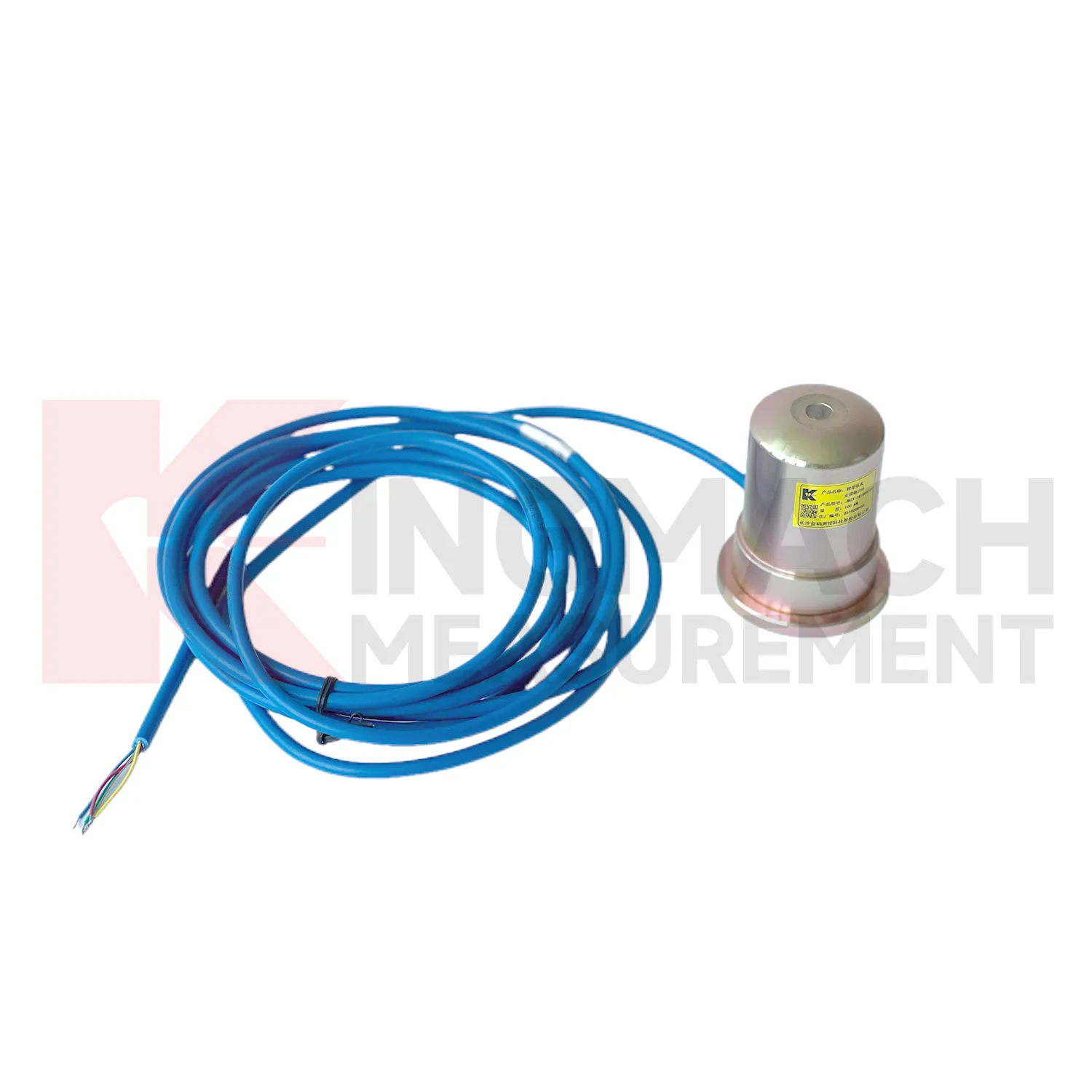
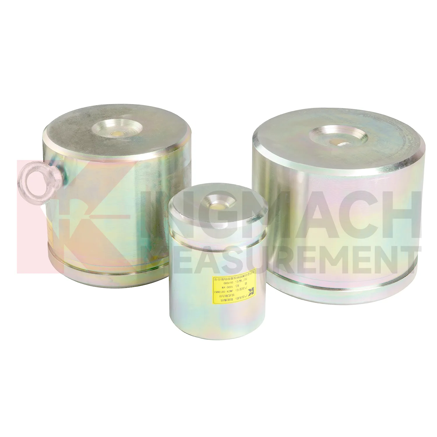
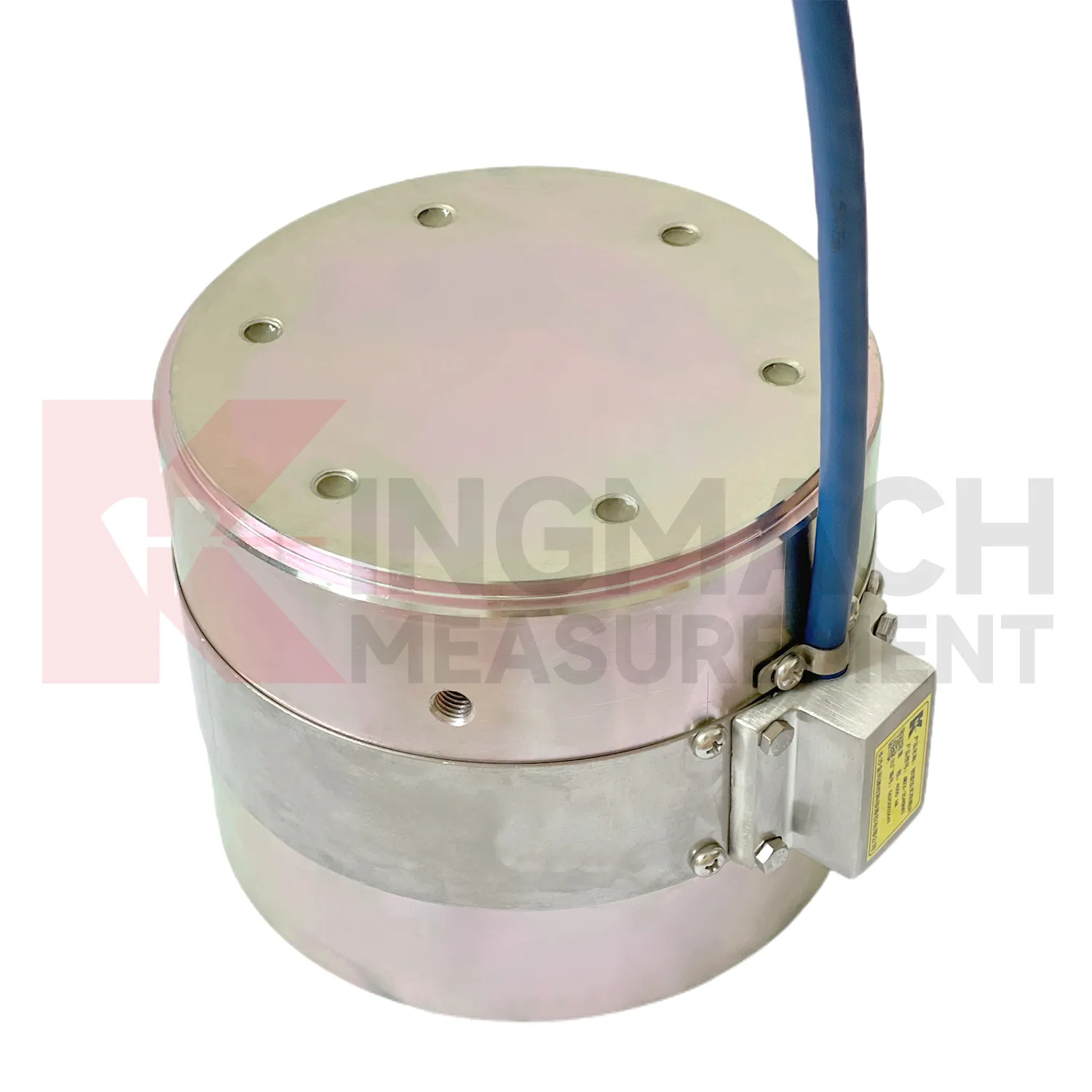
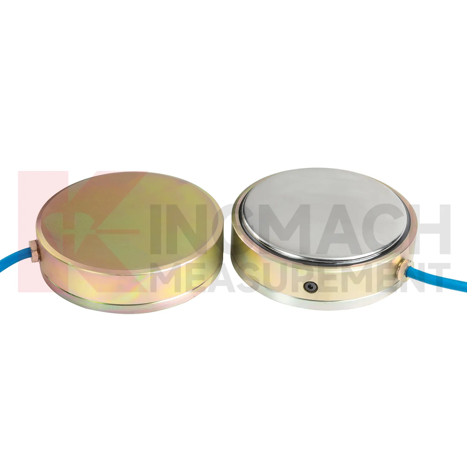
Kingmach diagram 4 wire load cell wire connection is developed for civil infrastructure where readings must remain usable after dust, vibration, water, and long cable runs enter the job. Product files describe vibrating wire based designs, smart chips, digital detection, strong anti-interference transmission, waterproof insulation, and automatic temperature correction. On the solid load cell JMZX-35XXHAT, the listed range runs from 1000 kN to 10000 kN with 0.1 kN resolution and 0.5%FS precision. On the hollow JMZX-3XXXHAT series, the listed range covers 500 kN to 8000 kN and the record memory can store 800 measurement entries. On the JMZX-38XXHAT axial force meter, the instrument can display axial force directly in kN. These details suit projects where force monitoring is part of acceptance, construction control, or long term service review. Kingmach's product grouping also supports mixed monitoring networks, where load readings sit beside water level, piezometer, displacement, settlement, and tilt data. For purchasing teams, this means the specification should include not only the sensor body, but also compatible readout equipment, cable length, protection accessories, calibration needs, and the reporting method expected by the owner. That reduces changes after the site work has already started. In practice, this means the specification should name the monitored member, expected reading frequency, installation exposure, and the person responsible for accepting the first stable value.
Application of diagram 4 wire load cell wire connection
In pile load testing and bearing capacity verification, diagram 4 wire load cell wire connection helps track applied force, load stages, unloading response, and residual behavior. The common problem is uncertainty around whether the applied load is centered and whether the recorded value matches the actual force passing through the test system. Kingmach solid load cells such as JMZX-35XXHAT list 1000 kN to 10000 kN ranges, 0.1 kN resolution, and 0.5%FS precision, with overload information listed as 20 to 50%F.S. range overload and 300 to 400%F.S. failure overload. These figures suit heavy test work when capacity margin must be checked before the sensor is installed. During the test, the record should include each loading step, hold time, unloading step, zero check, temperature, and any change to the bearing arrangement. Pairing the load record with settlement readings gives a clearer view of pile response. After the test, the documented calibration coefficient and instrument identity help keep the acceptance file defensible. Test reports should also record jack pressure, settlement response, load rate, hold duration, and any adjustment to the reaction system. These records help engineers identify whether an unusual load value came from the pile, the loading setup, or the measurement chain.
The future of diagram 4 wire load cell wire connection
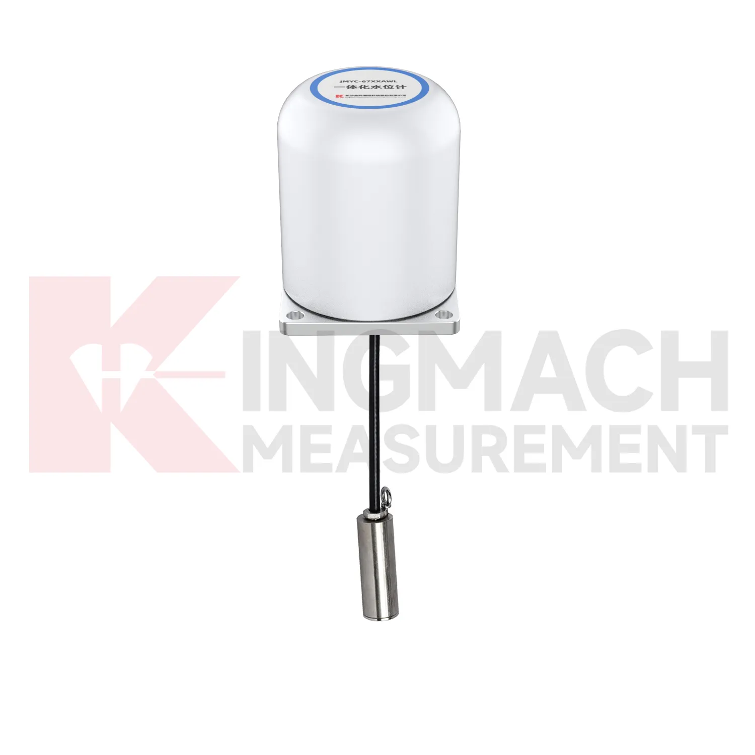
Geotechnical use of diagram 4 wire load cell wire connection will become more connected to environmental monitoring. Earth pressure cells with 0.3 MPa to 8 MPa ranges and 0.001 MPa resolution can already record soil or contact pressure, but future value comes from reading pressure with rainfall, groundwater, seepage, settlement, and slope movement. A pressure increase after rain may be acceptable in one slope and worrying in another, depending on the ground model and drainage condition. Digital twins can handle that comparison if the data is clean enough. Kingmach's wider catalog, including piezometers, water level meters, settlement sensors, tiltmeters, data loggers, and visualization software, supports that direction. Wireless communication will help remote slopes and embankments, while wired systems may remain preferable for buried points with long service expectations. Future standards for monitoring reports will likely ask for more traceable context around each reading, including sensor range, accuracy, calibration date, and installation depth. That connection makes trend review more useful after storms.
Care & Maintenance of diagram 4 wire load cell wire connection
For diagram 4 wire load cell wire connection used in pile load testing, care begins before the first load step. Confirm that the selected solid load cell range, often between 1000 kN and 10000 kN on Kingmach listed models, exceeds the planned test load with proper margin. Check the 0.1 kN resolution, 0.5%FS precision, calibration certificate, bearing plate flatness, and centering arrangement. During the test, protect the cable from jack movement and keep the readout position safe from vibration and water. Record zero value, temperature, load stage, hold time, unloading stage, and any pause or adjustment. After the test, inspect the sensor for dents, side load marks, connector damage, and cable jacket cuts. Store the calibration coefficient with the test report, not only with the instrument box. If later readings appear inconsistent, compare them with jack pressure, settlement data, and loading procedure before blaming the sensor. Store the report with the test file.
Kingmach diagram 4 wire load cell wire connection
diagram 4 wire load cell wire connection is not limited to weighing or lab testing. In Kingmach's project world, it is part of structural and geotechnical monitoring, where the object being measured may be a cable, a pier support, a pile, a retaining wall, a tunnel support, or a dam anchor. The instrument must survive rough installation and still return a clear force or pressure value. Capacity, sensitivity, accuracy, overload allowance, waterproofing, and temperature behavior all affect whether the data can be trusted months later. A sensor with the wrong range may flatten important changes or overload during construction. A sensor with poor protection may drift after water enters a connector. A sensor with unclear calibration records may create doubt during acceptance. The better approach is to match the instrument to the loading path and the reading method at the same time. That keeps procurement, installation, and data review working from the same assumptions. Those details keep the instrument useful after the original installation crew has left the site.
FAQ
Q: What does diagram 4 wire load cell wire connection do in a foundation pit or tunnel? A: It measures axial force in steel supports, anchor load, or pressure change as excavation and support stages progress. Q: Which Kingmach model fits steel support axial force? A: The JMZX-38XXHAT axial force meter is listed from 200 kN to 3000 kN, with 0.1 kN or 1 kN sensitivity and 0.5%FS accuracy. Q: Is it suitable for wet underground sites? A: The axial force meter lists a 1 MPa waterproof rating, but connector sealing and cable routing still need inspection. Q: Why is direct kN display useful? A: It reduces confusion because teams can read axial force directly instead of converting vibrating wire frequency on site. Q: What should trigger extra checks? A: Excavation step changes, rainfall, dewatering, support adjustment, sudden force jumps, or unstable channels.
Reviews
Michael Anderson
The strain gauges and load cells are extremely accurate and stable. They performed very well in our bridge monitoring project. Highly recommended!
David Wilson
We purchased displacement transducers and settlement sensors, and the quality exceeded our expectations. Easy installation and reliable performance.
Latest Inquiries
To protect the privacy of our buyers, only public service email domains like Gmail, Yahoo, and MSN will be displayed. Additionally, only a limited portion of the inquiry content will be shown.
Evelyn***@gmail.comSouth Africa
Hi, we are a contractor working on tunnel construction and need settlement sensors and displacement ...
Isabella***@gmail.comGermany
Hello, we are evaluating weir flow meters for a water management project. Please share accuracy deta...