 ar
ar bg
bg hr
hr cs
cs da
da nl
nl fi
fi fr
fr de
de el
el hi
hi it
it ko
ko no
no pl
pl pt
pt ro
ro ru
ru es
es sv
sv tl
tl iw
iw id
id lv
lv lt
lt sr
sr sk
sk sl
sl uk
uk vi
vi et
et hu
hu th
th tr
tr fa
fa ms
ms hy
hy ka
ka ur
ur bn
bn mn
mn ta
ta kk
kk uz
uz ku
ku
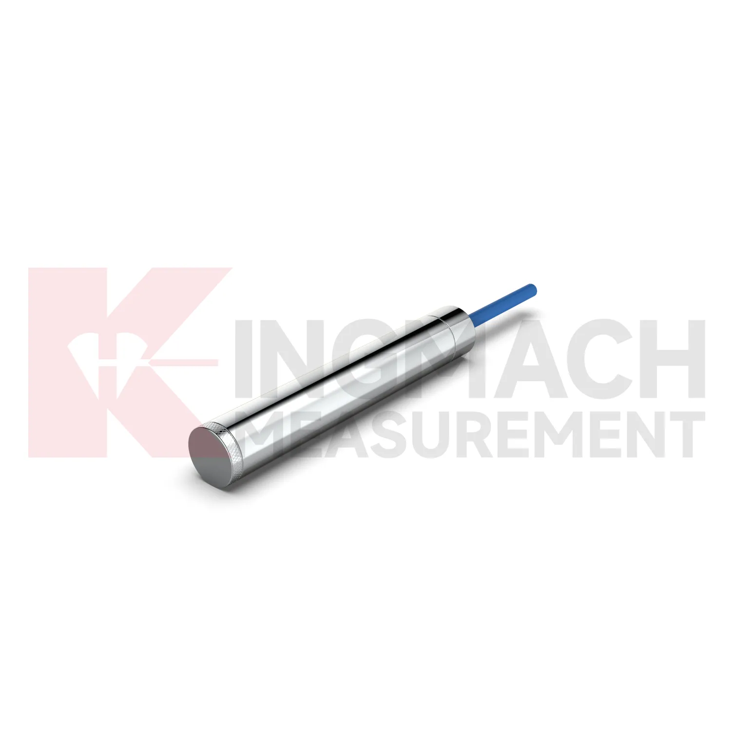
load cell connection diagram
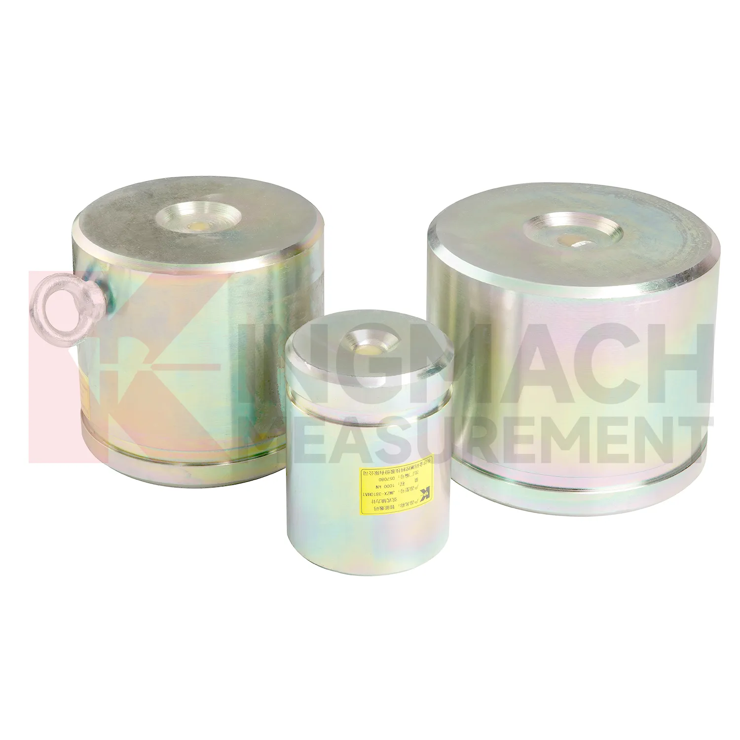
Kingmach load cell connection diagram is developed for civil infrastructure where readings must remain usable after dust, vibration, water, and long cable runs enter the job. Product files describe vibrating wire based designs, smart chips, digital detection, strong anti-interference transmission, waterproof insulation, and automatic temperature correction. On the solid load cell JMZX-35XXHAT, the listed range runs from 1000 kN to 10000 kN with 0.1 kN resolution and 0.5%FS precision. On the hollow JMZX-3XXXHAT series, the listed range covers 500 kN to 8000 kN and the record memory can store 800 measurement entries. On the JMZX-38XXHAT axial force meter, the instrument can display axial force directly in kN. These details suit projects where force monitoring is part of acceptance, construction control, or long term service review. Kingmach's product grouping also supports mixed monitoring networks, where load readings sit beside water level, piezometer, displacement, settlement, and tilt data. For purchasing teams, this means the specification should include not only the sensor body, but also compatible readout equipment, cable length, protection accessories, calibration needs, and the reporting method expected by the owner. That reduces changes after the site work has already started. In practice, this means the specification should name the monitored member, expected reading frequency, installation exposure, and the person responsible for accepting the first stable value.
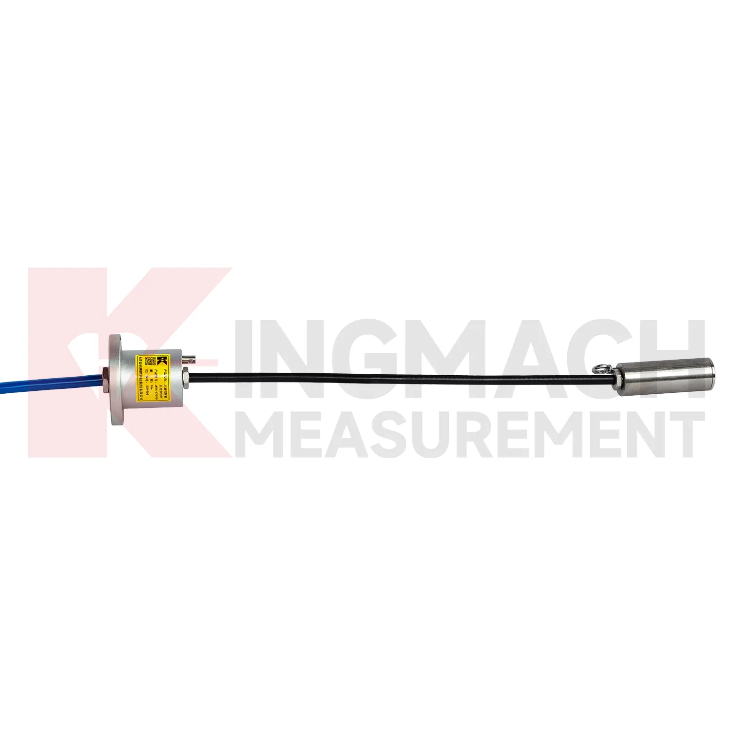
Application of load cell connection diagram
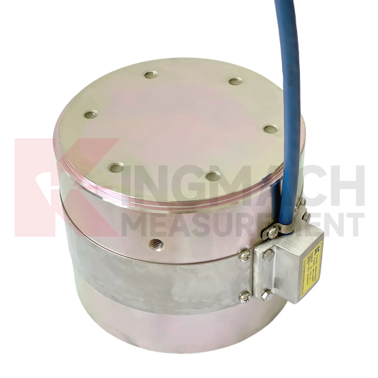
In foundation pit projects, load cell connection diagram supports strut force monitoring, anchor load control, retaining wall pressure checks, and load transfer review as soil is removed. The painful part of this work is timing: force can rise quickly after excavation, rainfall, dewatering, or support adjustment, while the working area is still changing every day. The axial force meter JMZX-38XXHAT covers 200 kN to 3000 kN and provides 0.5%FS accuracy with direct kN display. For soil pressure at retaining structures, the JMZX-50XXAT/ATM earth pressure cell line covers 0.3 MPa to 8 MPa with 0.001 MPa resolution and 0.5%FS pressure accuracy. These numbers give the monitoring team enough detail to track staged construction rather than only final condition. Good use also depends on bearing plates, adequate surface strength, cable protection, waterproof connectors, and a reading plan after each excavation layer. The force record should be compared with settlement, horizontal displacement, water pressure, and nearby construction notes. If automated monitoring is used, alarm thresholds should be tied to excavation stages rather than copied across all channels. A strut close to the active excavation face may behave differently from one several levels above, even when the same instrument model is used.
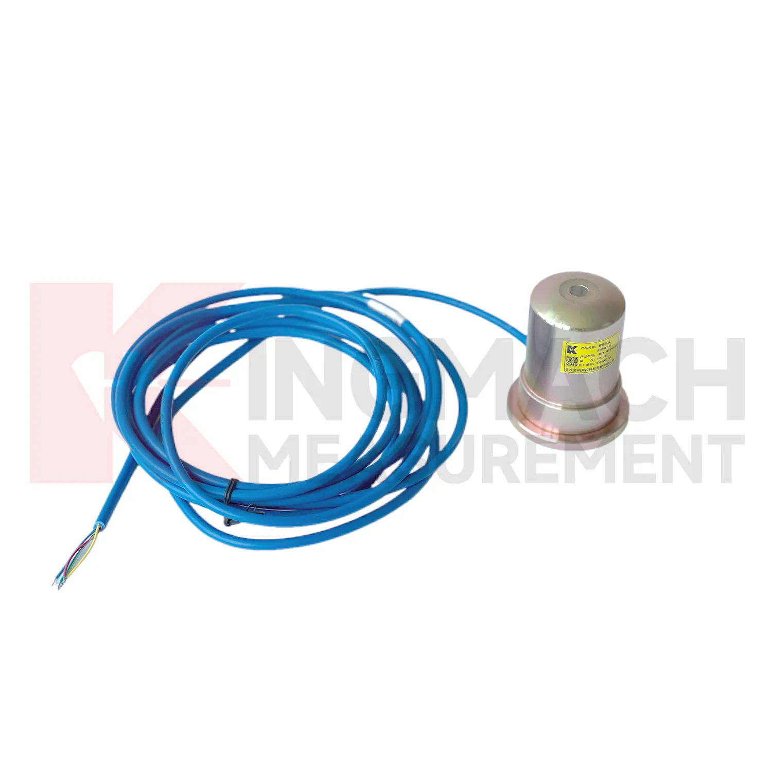
The future of load cell connection diagram
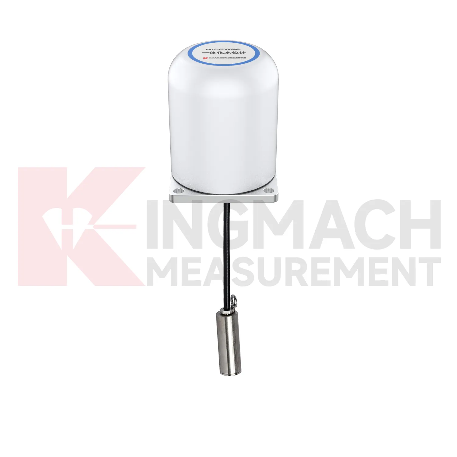
In tunnels and foundation pits, future load cell connection diagram use will move toward faster construction stage feedback. Axial force meters with 200 kN to 3000 kN ranges, 0.5%FS accuracy, direct kN display, and 1 MPa waterproofing already suit support load monitoring. The next step is pairing those readings with excavation depth, support installation time, groundwater level, wall displacement, and site progress records. LoRa or 4G gateways can reduce manual rounds where access is unsafe or work is moving too fast. Edge devices can flag missing channels, abnormal drift, or readings that changed after a cable was disturbed. This is different from a vague smart site label. It is a specific workflow where the sensor reading is checked against the work stage that should have caused it. As urban underground projects face stricter monitoring requirements, instruments that combine rugged installation, direct force output, and platform access will fit the way contractors actually manage risk.
Care & Maintenance of load cell connection diagram
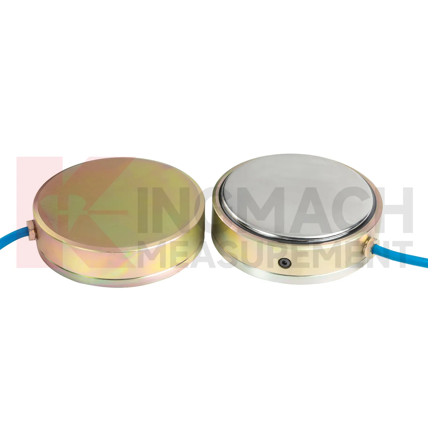
For load cell connection diagram installed in foundation pits or tunnels, the maintenance routine must fit a fast changing site. Axial force meters may cover 200 kN to 3000 kN with 0.5%FS accuracy and direct kN display, while earth pressure cells may cover 0.3 MPa to 8 MPa with 0.001 MPa resolution. During installation, confirm that steel support surfaces have enough thickness and strength, and add buffer plates where stress concentration is possible. Protect the sensor body and cable from equipment impact, cutting, concrete splash, and standing water. During excavation, check readings after each major stage rather than waiting for a fixed calendar date. If a channel becomes unstable, inspect the cable route, connector, readout, and temperature condition first. Long term points should have waterproof labels, photo records, and clear channel mapping. Sudden changes should be compared with wall movement, settlement, water pressure, and site work before any conclusion is recorded.
Kingmach load cell connection diagram
load cell connection diagram becomes most useful when the project treats it as part of a measurement chain. The chain starts with model selection and calibration, continues through surface preparation, installation, cable protection, readout setup, and first stable reading, then carries on through reporting and maintenance. Kingmach's range includes products with high capacity force measurement, waterproof construction, smart memory, direct kN display, and compatibility with readouts and automated acquisition systems. Those features only pay off when the field record is disciplined. The sensor should be named consistently, protected from mechanical damage, checked after loading events, and compared with nearby monitoring points. A force value that appears unusual should not be accepted or rejected in isolation. It should be checked against temperature, recent work, cable condition, connector sealing, and the last normal trend before a conclusion is made. That same record can later support warranty review, acceptance files, and maintenance planning. This is especially useful when the same point moves from construction control into long term asset monitoring.
FAQ
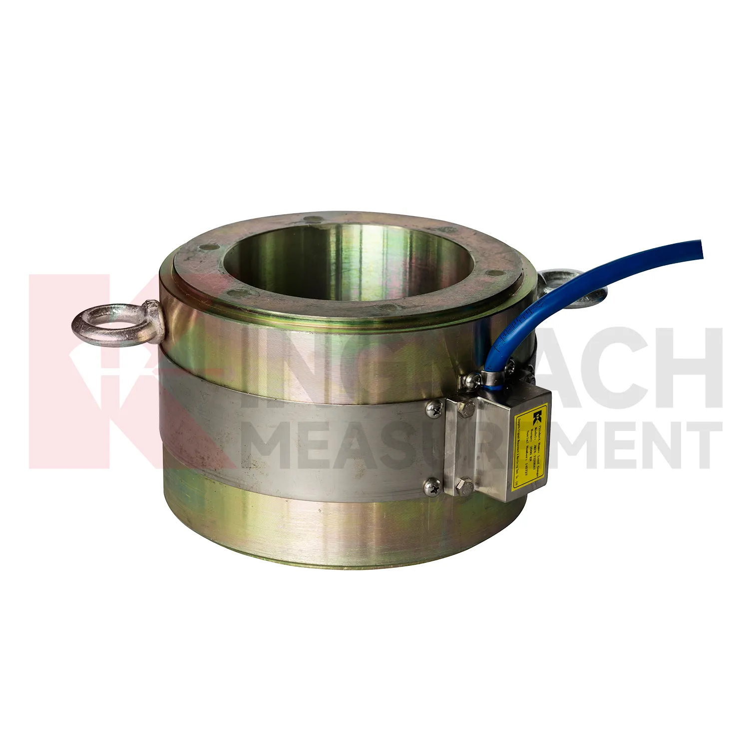
Q: How should load cell connection diagram be selected for a bridge cable or anchor point? A: Start with expected force, lock-off load, possible overload, bearing geometry, and access for later inspection. Hollow load cells are commonly used where the anchor or cable passes through the center opening. Q: What range information is available from Kingmach hollow models? A: The JMZX-3XXXHAT series is listed from 500 kN to 8000 kN, with 0.1 kN sensitivity on the 500 kN model and 1 kN on larger listed models. Q: Why does temperature correction matter? A: Cable and anchor readings can move with temperature, so built-in temperature measurement helps reduce false interpretation. Q: Can readings be stored inside the sensor? A: Smart hollow models list storage for 800 measurement records, including time, temperature, zero values, and correction data. Q: What should be checked after installation? A: Check seating, cable protection, connector sealing, zero value, first stable force, and matching channel name.
Reviews
Michael Anderson
The strain gauges and load cells are extremely accurate and stable. They performed very well in our bridge monitoring project. Highly recommended!
Andrew Lee
The visualization software is intuitive and powerful. It helps us analyze monitoring data efficiently.
Latest Inquiries
To protect the privacy of our buyers, only public service email domains like Gmail, Yahoo, and MSN will be displayed. Additionally, only a limited portion of the inquiry content will be shown.
Emma***@gmail.comCanada
Dear Sir/Madam, we are interested in displacement transducers and settlement sensors for a geotechni...
Harper***@gmail.comIndia
Dear Sir, we are planning to procure a complete monitoring system including strain gauges, tiltmeter...