
 EN
EN
 ar
ar bg
bg hr
hr cs
cs da
da nl
nl fi
fi fr
fr de
de el
el hi
hi it
it ko
ko no
no pl
pl pt
pt ro
ro ru
ru es
es sv
sv tl
tl iw
iw id
id lv
lv lt
lt sr
sr sk
sk sl
sl uk
uk vi
vi et
et hu
hu th
th tr
tr fa
fa ms
ms hy
hy ka
ka ur
ur bn
bn mn
mn ta
ta kk
kk uz
uz ku
ku
load cell wiring schematic
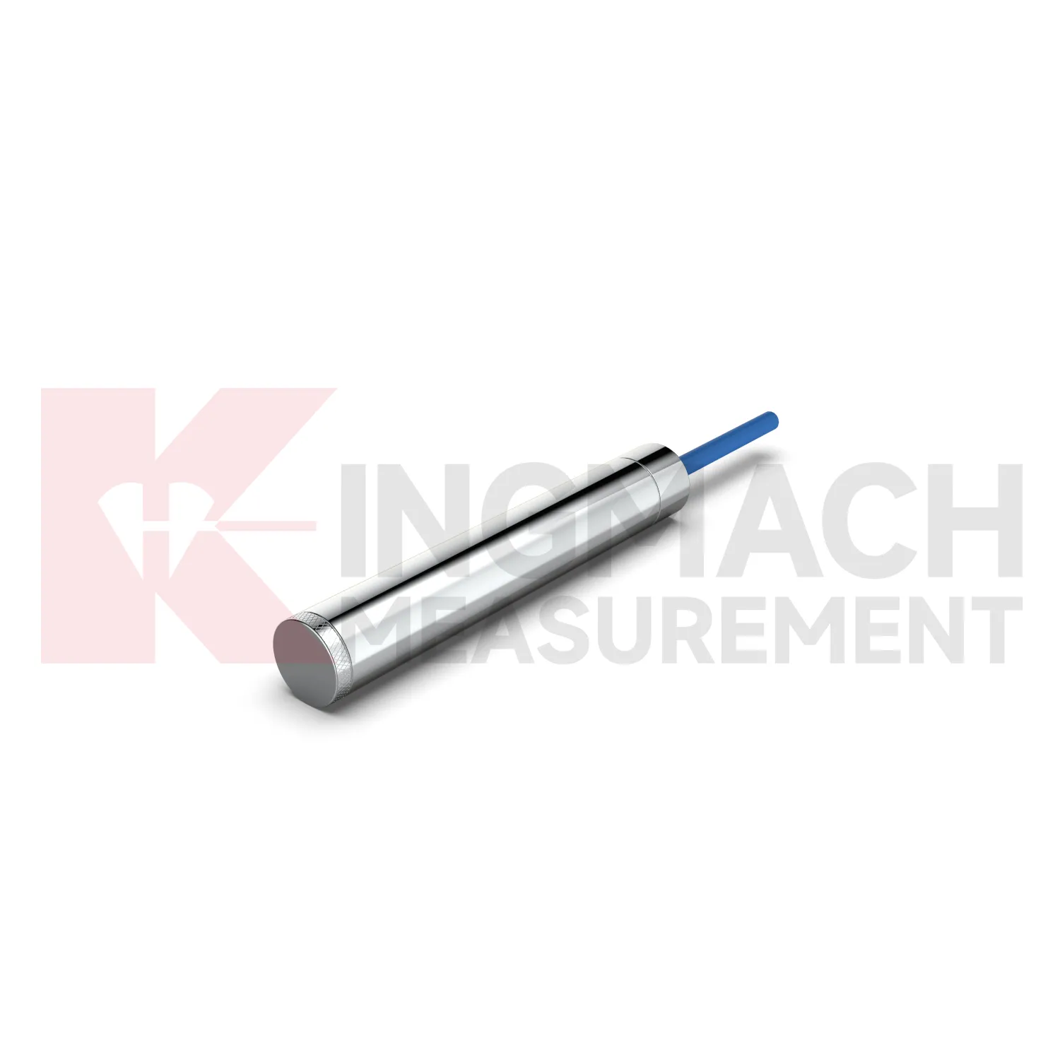
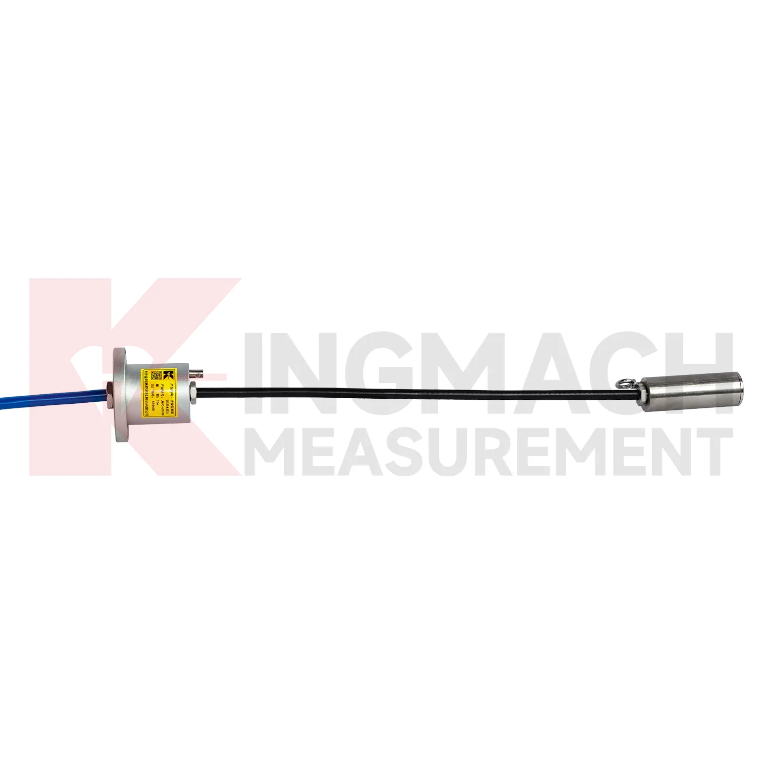
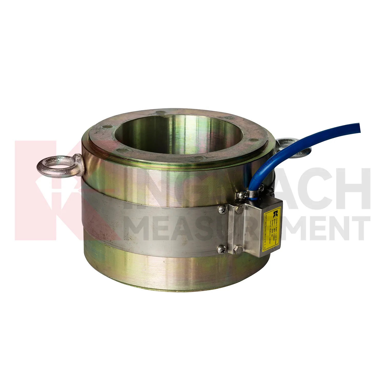
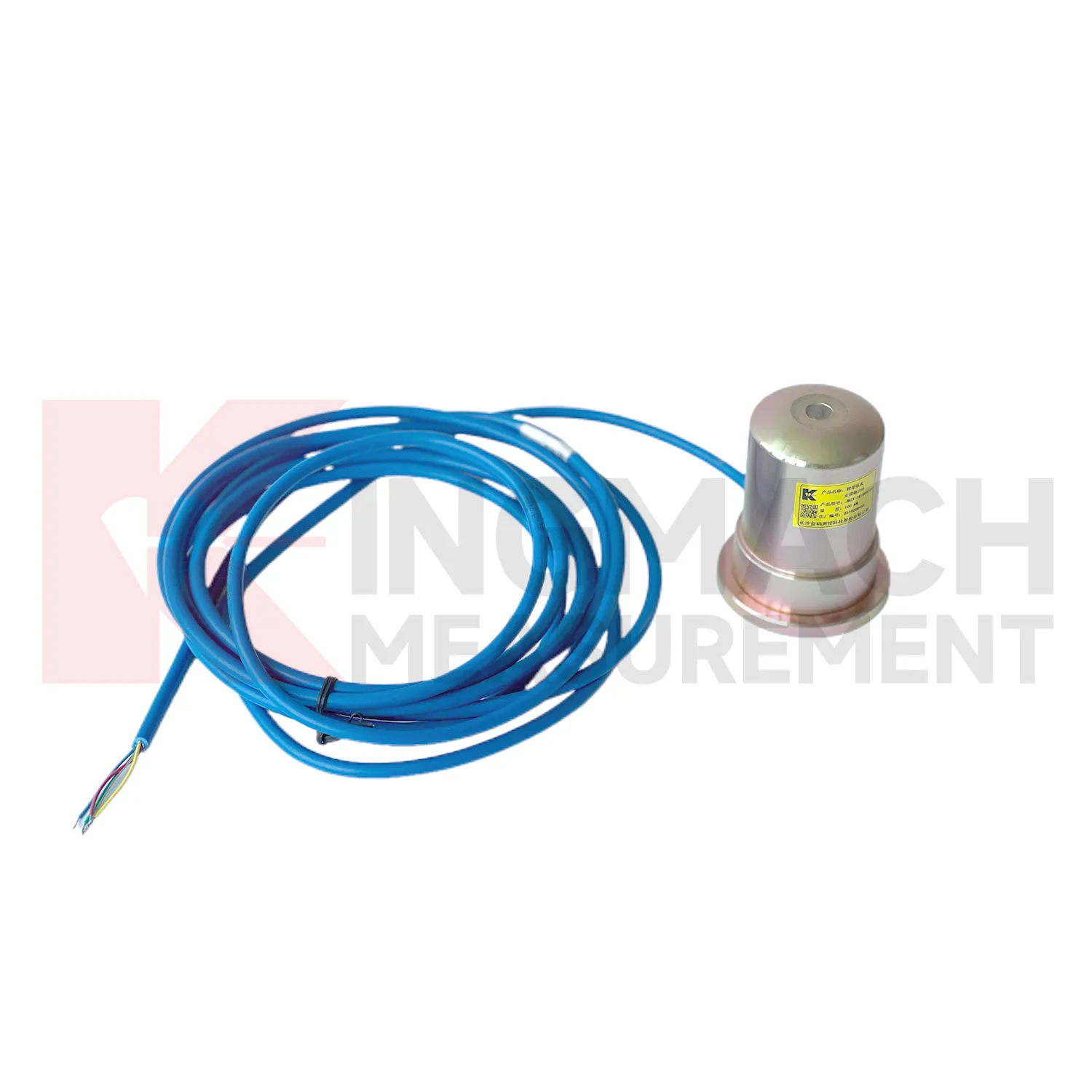
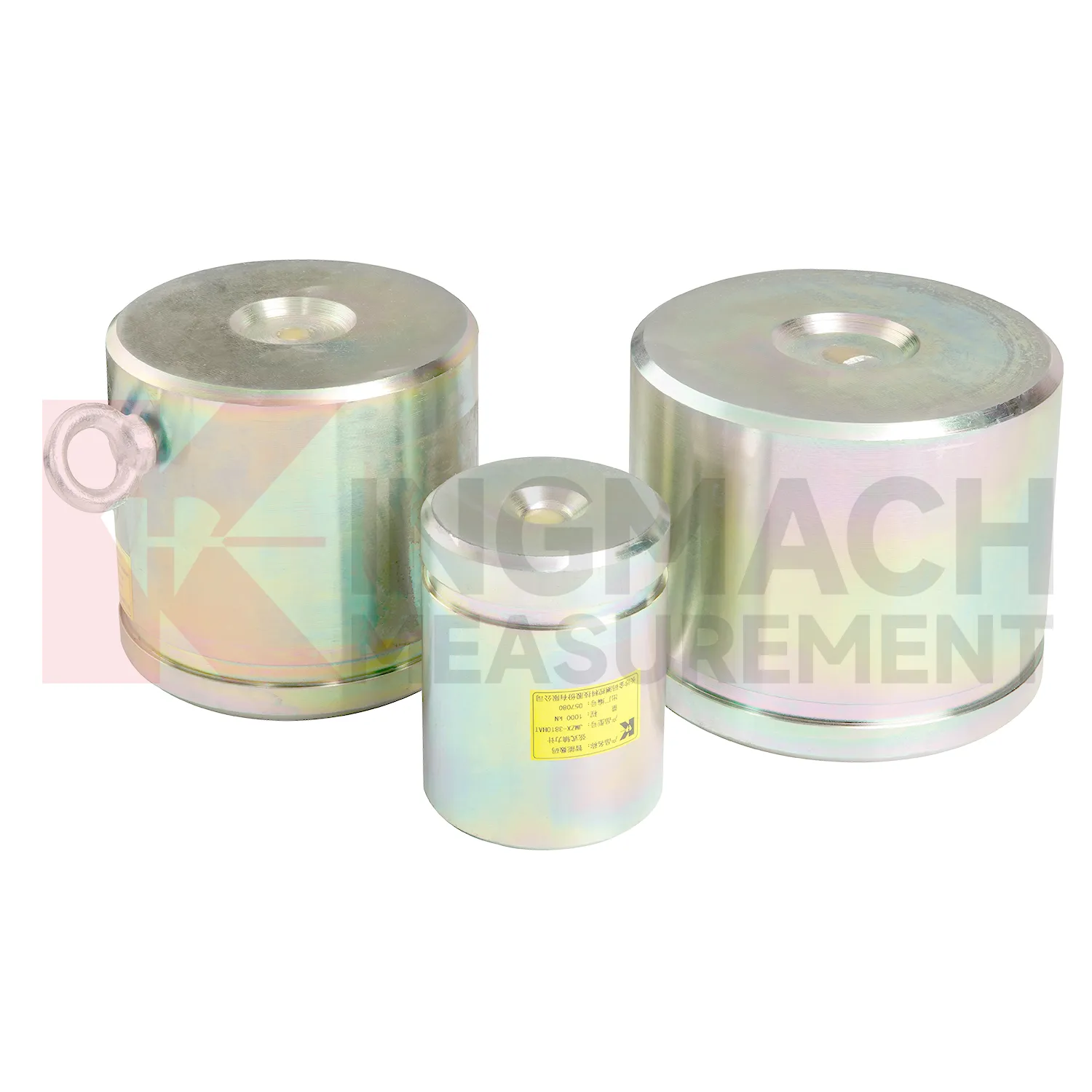
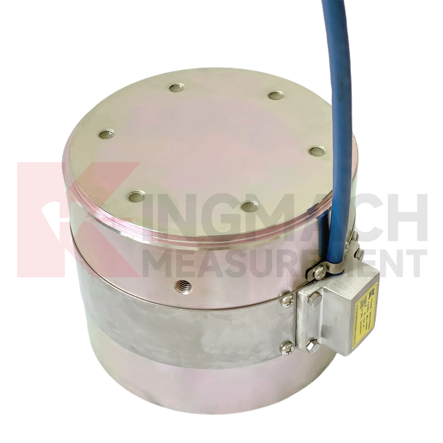
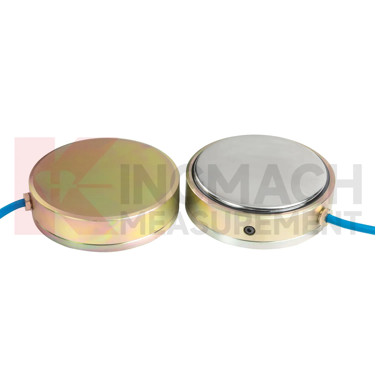
Kingmach load cell wiring schematic products give engineers several ways to measure load depending on the contact condition. Hollow load cells fit cable and anchor force work, solid load cells fit compression and bearing capacity checks, axial force meters fit steel support monitoring, and earth pressure cells fit soil or contact pressure measurement. The listed technical span is broad: 500 kN to 8000 kN for hollow models, 1000 kN to 10000 kN for solid models, 200 kN to 3000 kN for axial force meters, and 0.3 MPa to 8 MPa for earth pressure cells. Accuracy and resolution are also stated in the product files, including 0.5%FS precision on main force models and 0.001 MPa resolution for pressure cells. Kingmach adds practical field features such as waterproofing, temperature correction, memory storage, digital output, and compatible readout instruments. A good specification compares these numbers with the design load, possible overload, installation surface, service environment, and planned inspection interval. This brand context fits projects that combine several monitoring categories rather than one isolated load point. A bridge or foundation pit may require force, settlement, displacement, water pressure, and software records in the same maintenance file, so compatibility should be reviewed early. The data record should also state whether the pressure or force point will be checked manually, automatically, or by both methods during handover.
Application of load cell wiring schematic
In slope, embankment, and retaining wall projects, load cell wiring schematic helps monitor anchor force, slide resistant pile load, earth pressure, and stress change after rainfall or groundwater variation. The practical pain point is that visible slope movement may arrive late, while load and pressure trends may start earlier. Earth pressure cells in the Kingmach range are listed from 0.3 MPa to 8 MPa, with 0.001 MPa resolution, 0.5%FS pressure accuracy, and ±0.5°C temperature accuracy. Hollow load cells for anchor force cover 500 kN to 8000 kN and include temperature correction and waterproof construction. These parameters support long term points in buried, wet, or exposed conditions. Force data should be reviewed with inclinometer, settlement, water level, rainfall, and crack observation records. If anchor force drops while displacement increases, the project team has a different problem than a temporary pressure rise after rain. The instrumentation plan should therefore connect each load point to the ground behavior it is meant to explain. On slopes, cable routes should be protected against rockfall, drainage works, vegetation clearing, and surface runoff. Those mundane details matter because a broken cable can look like a dramatic geotechnical event if the hardware is not inspected first.
The future of load cell wiring schematic
Industrial and test bench use of load cell wiring schematic will likely move toward automated verification. High capacity solid load cells with 0.5%FS precision and ranges up to 10000 kN can already support heavy compression tests, jack calibration work, and equipment checks. Future systems can connect these instruments to local software that records test stages, operator notes, temperature, overload events, and calibration status. That reduces the risk of a handwritten record being separated from the force data. Edge acquisition can also prevent common errors by warning when the zero point is unstable, the load rate is outside procedure, or the sensor range is being approached too quickly. Kingmach's smart memory features fit this direction because the sensor can carry identity and calibration background. The strongest future workflow will combine rugged hardware, automatic records, and simple review tools, so a test can be repeated months later with the same measurement basis. The same logic applies to factory tests and site acceptance.
Care & Maintenance of load cell wiring schematic
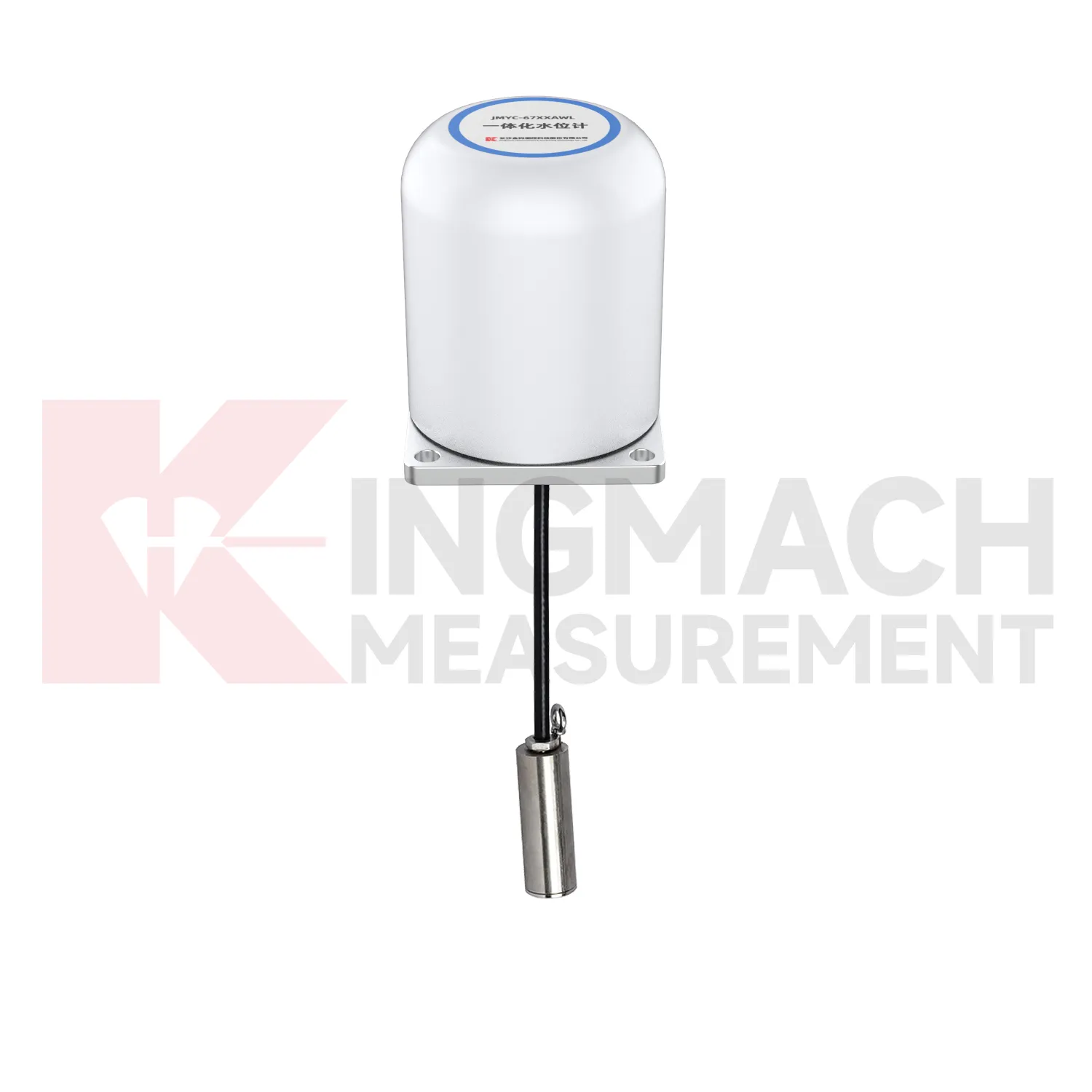
For load cell wiring schematic connected to automated acquisition, maintenance is partly physical and partly digital. At installation, confirm sensor model, range, channel number, unit, calibration coefficient, zero value, and temperature channel before the point is accepted. Smart load cells may store calibration information and up to 800 measurement records, while digital output and anti-interference transmission help long cable runs. During operation, review missing data, repeated identical values, sudden jumps, and temperature related drift. Physical checks should cover waterproof connectors, cable strain relief, grounding, lightning protection, junction boxes, and power supply stability. After any software or logger change, verify that kN or MPa units remain correct and that historical trends did not shift because of scaling errors. Where alarms are used, test the alarm path without applying dangerous loads. A good maintenance routine protects the instrument and the database at the same time, because either one can damage confidence in the monitoring record.
Kingmach load cell wiring schematic
load cell wiring schematic is often selected after a project team asks where force can change without being seen. In a tunnel, the answer may be the steel support. In a bridge, it may be a cable anchor or bearing. In a foundation pit, it may be a strut, anchor, or retaining wall contact zone. In a dam, it may be an anchor system affected by water level and temperature. Kingmach's monitoring product family allows these points to be linked with settlement sensors, displacement transducers, tiltmeters, piezometers, data loggers, and software platforms. That wider context matters because load change is rarely isolated. A rising force reading becomes more meaningful when it is checked against movement, pore pressure, and construction activity. A falling force reading may point to relaxation, seating loss, or damage near the bearing surface. The instrument gives the first clue, and the surrounding data explains it. It also makes abnormal values easier to discuss with designers, contractors, and maintenance teams.
FAQ
Q: How should load cell wiring schematic be selected for a bridge cable or anchor point? A: Start with expected force, lock-off load, possible overload, bearing geometry, and access for later inspection. Hollow load cells are commonly used where the anchor or cable passes through the center opening. Q: What range information is available from Kingmach hollow models? A: The JMZX-3XXXHAT series is listed from 500 kN to 8000 kN, with 0.1 kN sensitivity on the 500 kN model and 1 kN on larger listed models. Q: Why does temperature correction matter? A: Cable and anchor readings can move with temperature, so built-in temperature measurement helps reduce false interpretation. Q: Can readings be stored inside the sensor? A: Smart hollow models list storage for 800 measurement records, including time, temperature, zero values, and correction data. Q: What should be checked after installation? A: Check seating, cable protection, connector sealing, zero value, first stable force, and matching channel name.
Reviews
Daniel Brown
Excellent environmental monitoring sensors. The data is consistent, and the system integrates smoothly with our existing setup.
Michael Anderson
The strain gauges and load cells are extremely accurate and stable. They performed very well in our bridge monitoring project. Highly recommended!
Latest Inquiries
To protect the privacy of our buyers, only public service email domains like Gmail, Yahoo, and MSN will be displayed. Additionally, only a limited portion of the inquiry content will be shown.
Isabella***@gmail.comGermany
Hello, we are evaluating weir flow meters for a water management project. Please share accuracy deta...
Amelia***@gmail.comSingapore
Hello, I am looking for visualization software for monitoring system data analysis. Please let me kn...